SECTION XII-STEERING CLUTCHES AND CONTROLS
Topic Nos.
1
2

Topic Titles
General Description...............
Steering Clutches.................
Steering Clutch Throwout Bearing
Assemblies ....................
Steering Levers and Linkage........
Hydraulic Steering Control Housing . . .
Hydraulic Steering Pump...........
Hydraulic Steering System Piping ....
3 4 5 6 7
1. GENERAL DESCRIPTION
Each steering clutch is actuated by a hand lever which controls a hydraulic valve of the piston arrangement. The piston arrangement actuates the steering clutch throwoui bearing which in turn disengages the steering clutch.
Two steering clutches, one at each end of the bevel gear shaft, are employed for steering the tractor. Each steering clutch is enclosed in a brake drum which serves in conjunction with the steering clutch for steering, by braking the rotating action of the final drive.
2. STEERING CLUTCHES
ble operating conditions which determine the amount of clutch disc wear.
The steering clutch linkage is properly adjusted when the steering levers each have 2" of free travel, measured at the tops of the levers. As the clutch discs wear, this free travel decreases. When the free travel has decreased to 1", an adjustment of the clutch linkage is required. Free travel of the levers is necessary to insure proper clearance between the clutch throwout sleeve and the clutch throwout plate and to insure full engagement of each clutch.
C. Washing Steering Clutches.
Oil leaking into the steering clutch compartments may get on the clutch discs and cause the clutches to slip. If this occurs, wash the clutches in the following manner:
1. Install pipe plugs in the two drain holes in
the bottom of the steering clutch housing, at
each side of the bevel gear compartment
drain plug.

2. Remove the brake band adjusting nut covers
A. Description.
The two steering clutches, one on each side, are of the multiple disc type having sixteen (16) friction discs and sixteen (16) steel discs assembled alternately in each clutch assembly. Springs hold the discs tightly together in assembly between the pressure plate and the driving hub. The complete assemblies are contained in the brake drums.
Power is transmitted through these clutches from the bevel gear shaft to the final drive pinions. The steering clutches are disengaged by pulling back on the steering levers directly in front of the operator. This hydraulically forces a throwout sleeve against a throwout plate in the clutch and compresses the springs, thereby allowing the steel discs and friction discs to separate.
When either clutch is disengaged, the bevel gear shaft turns without driving or supplying power to the final drive pinion shaft on the side disengaged.
B. Clutch Service.
Specified time intervals between linkage adjustments can not be established because of the varia-
198
remove, then remove the brake band lever. Do not remove the brake band as it will be used in lifting the steering clutch and brake drum assembly.
7. Remove the capscrews attaching the steering
clutch assembly to the driving hub and the
brake drum hub. This will necessitate turn-
ing the clutch assembly and brake drum
which can be accomplished by inserting a
suitable bar in one of the ventilating holes
in the brake drum.

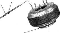
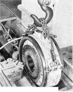
8. Using a chain hooked around the brake band
adjuster and around a yoke pin placed in
the lower end of the band, lift the steering
clutch assembly and brake drum out of the
compartment as shown in Figure No. 1.

from the top of the housing and pour about three gallons of solvent into each compartment. Drive the tractor back and forth in a straight line for approximately five minutes, leaving the steering clutches engaged. The oil on the exterior of the clutches and brakes will be washed off in this operation.
3. Drain the compartments and refill with the
same amount of solvent, then drive the trac-
tor back and forth for approximately another
five minutes, disengaging one clutch and
then the other continually during this period.
Disengaging the clutches allows the clutch
discs to separate so that the solvent can get
in between the discs to wash the oil from
their friction surfaces.

4. Drain the compartments and allow the
clutches a short time to dry. Operate the
tractor with a light load in low gear until
the clutches become thoroughly dry, other-
wise they may slip due to the presence of
solvent on the discs.

ID. Clutch Removal.
1. Remove the fuel tank (refer to "FUEL TANK
REMOVAL" in Section II).

2. Remove the center and rear floor plates.
3. Remove the jam nut, and the brake band
support adjusting nut.

4. Remove the steering clutch compartment
covers.

5. Turn the brake band adjuster counter-clock-
wise untii it is loosened from the brake band
adjusting fork.

6. Remove the yoke pin connecting the brake
rod yoke assembly to the brake band lever.
Remove the pipe plug located in the side of
the steering clutch case in line with the brake
band pin, and using a suitable 3/8" N.C.
capscrew inserted through the hole, turn it
into the tapped hole in the end of the pin.
Now pull the brake band adjusting fork pin
out and remove the brake band adjusting
fork. Lift up on the brake band lever until
the pin attaching the lower end of the band
to the lever, can be removed. Push the pin
towards the bevel gear compartment and

strclutch2-1.jpg
strclutch2-2.jpg
Vtl __ ..
Fig. 1—Removing Steering Clutch
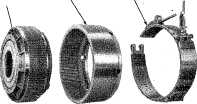
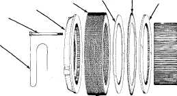
I. Disassembly of Steering Clutches.
1, Remove the drum from the clutch assembly
being careful not to bend the clutch disc
teeth.

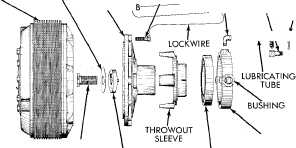
2. Before disassembling the clutch, center punch
the pressure plate, the back plate, the hub,
and the throwout plate so that they can be
reassembled in the same position as they
were before disassembly.

199
3. Remove the lockwires and five (5) of the ten
(10) drilled head capscrews used in holding
the clutch together (every other one). NOTE:
It will be necessary to use five (5) studs to
hold the load of the compressed steering
clutch springs when disassembling the steer-
ing clutch. Each stud should be 1/2" diam-
eter by 11%" long, having one end threaded
1/2" N.F. for a distance of approximately
1". The other end should be machined
square for a wrench hold and threaded 1/2"
N.F. for a distance of approximately 81/2".

4. Install the five studs with the short threaded
end into the throwout plate, followed by flat
washers and hex nuts. Screw the nuts down
against the pressure plate. Refer to Figure
No. 3.

5. Remove the remaining capscrews, then loosen
the stud nuts evenly until all tension is taken
off the clutch springs.

6. The throwout plate, discs, springs, etc., can
now be removed.

BRAKE DRUM BRAKE BAND
STEERING CLUTCH

strclutch2-3.jpg
ASSEMBLY
Fig. 2 — Steering Clutch, Brake
Drum and Brake Band

WASHER SPECIAL STUDS
strclutch2-4.jpg
NUT
SPRING
THROWOUT PLATE
Fig. 3 — Disassembly of Steering Clutch
BI-METALLIC DISC PRESSURE SPRING

DISC STACK STEEL DISC |
\ SPACER
strclutch2-5.jpg
BACK PLATE
strclutch2-6.jpg
PRESSURE. PLATE CAPSCREW
LOCK WIRE
j \ THROWOUT PLATE

STEERING CLUTCH
STEERING CLUTCH HUB

ASSEMBLY LOCKING WASHER
DRIVING HU
strclutch2-7.jpg
CAPSCREW _ STREET n____--YOKE BALL
w
WICK
strclutch2-8.jpg
aaixmrnm^ I!
LOCKING
D] /-)p|/
/I -\ I CAPSCREW
TRUNNION PIN WEAR PIN
HUB BOLT
BEARING CAGE
THROWOUT YOKE
WASHER ASSEMBLY BALL BEARING
.Fig. 4 —Steering Clutch and Throwout Yoke Details_
200
throwout plate are in line.
6. Place the back plate on the hub. Be certain
that the center punch marks on these parts
are in line.

7. Stack the discs (16 each friction and steel)
alternately on the hub beginning with a fric-
tion disc next to the back plate. Line up the
external teeth as near as possible.

8. Lay the pressure plate in place, being cer-
tain that the center punch mark on the
pressure plate lines up with the others, and
install the five (5) special studs (studs used
in disassembly of clutch) into the throwout
plate.

9. Place the brake drum over disc stack, then
turn the nuts down on the studs, forcing the
pressure plate down, until the assembly is
securely bolted together.

10. Using a suitable scale or straight edge,
measure the distance between the machine
finished end face of the hub, and the ma-
chined finished face of the throwout plate.
These faces must be in line within 1/16".
Add steel discs as required to obtain the
desired 1/16" measurement; placing them
next to the pressure plate.

11. Install five (5) attaching capscrews and
tighten them, then remove the five (5) special
studs and install the five (5) remaining cap-
screws. Tighten the ten (10) capscrews se-
curely and install the lockwire.

H. Clutch Installation.
The installation of the clutch may be made by direct reversal of the procedure outlined under "CLUTCH REMOVAL" in this section. Adjust the clutch linkage as explained in "STEERING LEVERS AND LINKAGE" in this section.
F. Clutch Inspection and Repairs
When the clutches have been disassembled, inspect
the following items:

1. Steel Discs.
Specified thickness when new is .084" to .096". Inspect the discs for wear and scoring. The discs must be flat within .015".
2. Friction Discs.
The specified thickness when new Js .152" to .157". Inspect the discs for wear, condition of teeth, and scoring. If the thickness of discs is less than .125", or the teeth are in bad condition, new discs must be installed.
3. Pressure Springs.
Each pressure spring when new exerts a pressure of 320 to 340 pounds when compressed to 5-3/64". If a spring does not check reasonably close to this tolerance, it is an indication that it has lost its tension and a new spring should be installed.
4. Hub.
Inspect the hub splines for wear as heavy grooving may cause binding of the teeth of the steel discs in the hub splines.
G. Assembly of Steering Clutch.
Refer to Figure No. 4 showing the parts in their
relative position.

1. Lubricate the hub teeth and the extreme outer
surface of the throwout plate sparingly with
a supremalube or its equivalent.

2. Place the throwout plate on a bench with
the spring bosses up.

3. Install a spring over each boss and install a
spacer in each spring.

4. Place an insulating washer on each spring.
5. Place the hub over the springs. Be certain
that the center punch marks on the hub and

3. STEERING CLUTCH THROWOUT BEARING ASSEMBLIES
A. Description.
Each steering clutch throwout bearing assembly consists of the following parts: throwout ball bearing, throwout bearing cage, throwout bearing
sleeve, throwout yoke assembly, and a lubricating wick. The ball bearing is a press fit in the throwout bearing cage, and on the hub of the throwout bearing sleeve. The throwout sleeve and bearing
201